1. Kondisi [kembali]
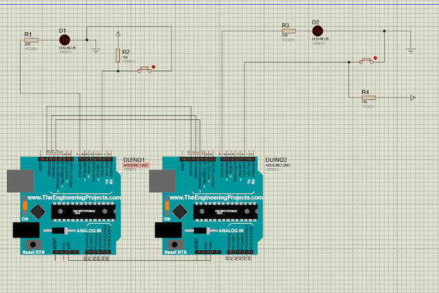
2. Rangkaian Simulasi [kembali]
Master Arduino Code:
//SPI MASTER (ARDUINO)
#include<SPI.h> //Library for SPI
#define LED 7
#define ipbutton 2
int buttonvalue;
int x;
void setup (void)
#define LED 7
#define ipbutton 2
int buttonvalue;
int x;
void setup (void)
{
Serial.begin(115200); //Starts Serial Communication at Baud Rate 115200
pinMode(ipbutton,INPUT); //Sets pin 2 as input
pinMode(LED,OUTPUT); //Sets pin 7 as Output
SPI.begin(); //Begins the SPI commnuication
SPI.setClockDivider(SPI_CLOCK_DIV8); //Sets clock for SPI communication at 8 (16/8=2Mhz)
digitalWrite(SS,HIGH); // Setting SlaveSelect as HIGH (So master doesnt connnect with slave)
}
void loop(void)
{
byte Mastersend,Mastereceive;
{
byte Mastersend,Mastereceive;
buttonvalue = digitalRead(ipbutton); //Reads the status of the pin 2
if(buttonvalue == HIGH) //Logic for Setting x value (To be sent to slave) depending upon input from pin 2
{
x = 1;
}
else
{
x = 0;
}
digitalWrite(SS, LOW); //Starts communication with Slave connected to master
Mastersend = x;
Mastereceive=SPI.transfer(Mastersend); //Send the mastersend value to slave also receives value from slave
if(Mastereceive == 1) //Logic for setting the LED output depending upon value received from slave
{
digitalWrite(LED,HIGH); //Sets pin 7 HIGH
Serial.println("Master LED ON");
}
else
{
digitalWrite(LED,LOW); //Sets pin 7 LOW
Serial.println("Master LED OFF");
}
delay(1000);
}
{
x = 1;
}
else
{
x = 0;
}
digitalWrite(SS, LOW); //Starts communication with Slave connected to master
Mastersend = x;
Mastereceive=SPI.transfer(Mastersend); //Send the mastersend value to slave also receives value from slave
if(Mastereceive == 1) //Logic for setting the LED output depending upon value received from slave
{
digitalWrite(LED,HIGH); //Sets pin 7 HIGH
Serial.println("Master LED ON");
}
else
{
digitalWrite(LED,LOW); //Sets pin 7 LOW
Serial.println("Master LED OFF");
}
delay(1000);
}
Slave Arduino Code:
//SPI SLAVE (ARDUINO)
//SPI SLAVE (ARDUINO)
#include<SPI.h>
#define LEDpin 7
#define buttonpin 2
volatile boolean received;
volatile byte Slavereceived,Slavesend;
int buttonvalue;
int x;
void setup()
#define LEDpin 7
#define buttonpin 2
volatile boolean received;
volatile byte Slavereceived,Slavesend;
int buttonvalue;
int x;
void setup()
{
Serial.begin(115200);
pinMode(buttonpin,INPUT); // Setting pin 2 as INPUT
pinMode(LEDpin,OUTPUT); // Setting pin 7 as OUTPUT
pinMode(MISO,OUTPUT); //Sets MISO as OUTPUT (Have to Send data to Master IN
Serial.begin(115200);
pinMode(buttonpin,INPUT); // Setting pin 2 as INPUT
pinMode(LEDpin,OUTPUT); // Setting pin 7 as OUTPUT
pinMode(MISO,OUTPUT); //Sets MISO as OUTPUT (Have to Send data to Master IN
SPCR |= _BV(SPE); //Turn on SPI in Slave Mode
received = false;
received = false;
SPI.attachInterrupt(); //Interuupt ON is set for SPI commnucation
}
}
ISR (SPI_STC_vect) //Inerrrput routine function
{
Slavereceived = SPDR; // Value received from master if store in variable slavereceived
received = true; //Sets received as True
}
{
Slavereceived = SPDR; // Value received from master if store in variable slavereceived
received = true; //Sets received as True
}
void loop()
{ if(received) //Logic to SET LED ON OR OFF depending upon the value recerived from master
{
if (Slavereceived==1)
{
digitalWrite(LEDpin,HIGH); //Sets pin 7 as HIGH LED ON
Serial.println("Slave LED ON");
}else
{
digitalWrite(LEDpin,LOW); //Sets pin 7 as LOW LED OFF
Serial.println("Slave LED OFF");
}
buttonvalue = digitalRead(buttonpin); // Reads the status of the pin 2
if (buttonvalue == HIGH) //Logic to set the value of x to send to master
{
x=1;
}else
{
x=0;
}
Slavesend=x;
SPDR = Slavesend; //Sends the x value to master via SPDR
delay(1000);
}
}
5. Video [kembali]
6. Link Download [kembali]
- Simulasi Proteus Link Download
- Listing Program
- Master dan Slave
- Video Link Download
.


Tidak ada komentar:
Posting Komentar